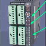
EZ-ZONE® Rail-Mount Control Module (RMC)
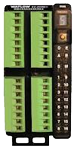
Control Module Specifications (RMC)
(Select an RMC module for 1 to 4 loops of control.)
Requires 24 to 28VAC/VDC power supply, includes communication port for configuration with EZ-ZONE configurator and PC.