EZ-ZONE® Access Module (RMA)

EZ-ZONE® Access Module (RMA)

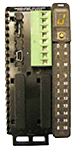
Select each feature to view available options for the Rail-Mount Access Module..

Access Module Specifications (RMA)

(Select an RMA module for communication protocol options, datalogging and automatic configuration backup.)

Access module requires a Class 2 or SELV power supply 20.4 to 30.8 V ~(ac) / (dc), communication port for configuration with EZ-ZONE Configurator software.

    Line Voltage/Power

  • Power consumption: 4 W, 9VA
  • Any external power supply used should comply with a Class 2 or SELV rating
  • Isolated Serial Communications

  • All modules ship with standard bus protocol for configuration and communication connection to all EZ-ZONE products
  • Additional Communication Options

  • EIA 232/485, Modbus® RTU
  • EtherNet/IP™, Modbus® TCP, 10 BASE-T/100 BASE-TX
  • DeviceNet™
  • PROFIBUS DP (future option, contact factory)
  • USB, controller recognized as a device
  • Note: If an access module is present, all other modules must have Modbus® disabled in order to achieve communications with all of the modules.
    USB

  • USB 1.1 device only
  • Mini USB connector type
  • Recognized as a mass storage device
  • Real Time Clock with Battery Backup

  • Accuracy (typical): +/- 30ppm at 77°F (25°C)
  • +30/-100ppm overtemperature operating range
  • Battery type and typical lifetime rating: 10 years at 77°F (25°C)
  • Lithium battery used, recycle properly

Data Logging

  • 200 points
  • File storage on-board module
  • Common separated value (CSV) file type
  • Export files via removable SD micro memory card or USB communications port
  • Memory Card

  • Removable SD micro card
  • 2G SD memory card provided, also accepts other storage space amounts
  • -4 to 185°F (-20 to 85°C) ambient rating, non-volatile memory
  • Information access to configuration files and the ability to store module auto-configuration settings and datalog files if options have been ordered
  • Auto-configuration File Backup

  • Limited memory can support up to four modules
  • Limited memory is fixed on board
  • Unlimited memory can support up to 16 modules
  • Unlimited memory utilizes removable SD micro card option
  • Note: All module parameters are backed up in memory except for USER SET 1 and USER SET 2 parameter settings and address.


    (4) Connector Style
    A = Right angle screw connector (standard)
    F = Front screw connector
    S = Custom


    (5) Future Options
    A = standard


    (6) Communications Options
    A = None
    2 = Modbus® RTU 232/485
    3 = EtherNet/IP™ Modbus®/TCP
    5 = DeviceNet™
    6 = Profitbus DP


    (7) Ramp/Soak Functions
    A = None
    F = Battery backup and real time clock for profile ramp and soak


    (8) System Configuration & Data Logging Options
    Order Option SB Device Comms. Limited Configuration File Back-up, Maximum 4 Modules Unlimited Auto Configuration File Back-up, Maximum 16 Modules On-Board Data Loggin Mobile Data
    A
    B
    Y
    D

    USB Device Configuration = USB access to configuration files (and data log files if data logging option is ordered) stored via on-board SD memory card. PC access to product via Standard Bus protocol.
    Auto-Configuration Backup = Limited fixed on board memory can support backing up configuration files for a maximum of 4 modules. The unlimited option utilizes a SD memory card to enable configuration file backup for up to 16 modules. Feature can be used for cloning configuration files to multiple modules or for easy field replacement to limit downtime.
    Data Logging = Data log files stored on 2G SD memory card. Data files can be exported via USB communication port transfer or removing SD card into external card reader. Watlow reserves the right to ship a larger memory amount at any point in time. Mobile Data: Transfer configuration files (and data logging files if data logging option is ordered) via removable SD memory card.


    (9)(10) Future Options
    A = standard
    A = standard


    (11)(12) Additional Options
    AA = Standard
    AB = Replacement connectors hardware only for the entered model number
    12 = Class 1, Div. 2 (not available with integrated limit controller or mechanical relay options)
    XX = Custom