EZ-ZONE® RM Mulit-Loop Controllers
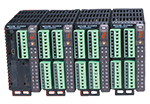
EZ-ZONE® RM Controller Modules can provide from 1 to 152 Loops of Integrated Temperature, Process, Limit & Power Control.
The EZ-ZONE® RM controller family simplifies thermal system management. The EZ-ZONE RM controller family is comprised of six module types: an integrated on-off or PID control, monitoring and over/under temperature limit module, a high-density on-off or PID control module, a high-density limit only module, an input/output (I/O) expansion module, a high-density monitor/scanner module and a data logging and field communications access module. A system is configured by connecting any combination of module types to address specific application needs. The EZ-ZONE RM is extremely flexible and scalable allowing mixing and matching of I/O to configure 1 to 152 control loops and up to 256 monitor points.
Optional integrated controller functions can be combined or ordered in different quantities:
- PID control loops
- Over/under temperature limit control loops
- 10 and 15 ampere power output/heater driver options
- On-board data logging
- Current measurement input
- Sequencer start up and control function
- Programmable timer and counter functions
- Programmable math and logic options
- Multiple communication protocols options
- Mobile configuration with removable secure digital (SD) flash card
Benefits of using an integrated controller solution:
- Reduces wiring time and termination complexity compared to connecting multiple discrete products
- Improves system reliability
- Reduces termination and installation cost
- Eliminates compatibility issues often encountered with using various discrete components and brands
- Reduces troubleshooting time and downtime costs because the system can specifically identify any problems with a sensor, controller, solid state relay (SSR) power output or heater load
- Complete thermal solution saves engineering time and labor costs while shortening project schedules
Features and Benefits
Multiple inputs; from 1 to 152 PID loops of control or monitor up to 256 analog inputs
- Mix and match I/O to fit any application; from 1 input with 2 outputs to 152 analog inputs with 152 outputs, or monitor up to as many as 256 analog inputs all in one system
- Reduces cost because only required loops are purchased
- Allows a common controller platform across many design applications as both loops and outputs can be ordered in single increments
Advanced PID control algorithm
- Offers TRU-TUNE®+ adaptive control to provide tighter control for demanding applications
- Enables auto-tune for fast, efficient start-up Communication capabilities
- Provides a range of protocol options including universal serial bus (USB) device port, Modbus® RTU, EtherNet/IP™, Modbus® TCP, DeviceNet™ and PROFIBUS USB Port
- Provides data log retrieval SPLIT-RAIL control
- Allows modules mounted in separate high-voltage and low-voltage cabinets to function as an integrated system
- Minimizes the length and cost of wire runs and improves system reliability by locating inputs closer to sensors and outputs closer to loads AUTO CLONE
- Reduces time and configuration complexity by automatically building a new module with the same parameter settings as the replaced module SENSOR GUARD
- Prevents unplanned process shutdowns and product loss by switching to a backup sensor if the primary sensor fails
Additional Key Functions
- Configuration communication port (standard bus)
- Removable modules and connectors
- Ring lug and front-screw terminal options
- Profile ramp soak with 400 total steps
- Retransmit and remote set point input virtually inside controller eliminating costs for input/output hardware
- User configuration settings can be stored and recalled
- Thermistor input
- Elevated operating range of 0 to 149°F (-18 to 65°C)
- UL® listed, CSA, CE, RoHS, W.E.E.E. FM, SEMI F47-0200, Class 1, Div. 2 rating on selected models
Common Specifications (Applies to all modules)
Line Voltage/Power
- 20.4 to 30.8VAC/VDC, 50/60Hz ±5%
- Any external power supply used should comply with a Class 2 or SELV rating (see specific module specification listing for max. VA power consumption)
- Data retention upon power failure via non-volatile memory
- Compliant with Semi F47-0200, Figure R1-1 voltage sag requirements
Environment
- 0 to 149°F (-18 to 65°C) operating temperature
- -40 to 185°F (-40 to 85°C) storage temperature
- 0 to 90% RH, non-condensing
Functional Operating Range for RMC, RMH, RML and RMS
- Type J: -346 to 2192°F (-210 to 1200°C)
- Type K: -454 to 2500°F (-270 to 1371°C)
- Type T: -454 to 750°F (-270 to 400°C)
- Type E: -454 to 1832°F (-270 to 1000°C)
- Type N: -454 to 2372°F (-270 to 1300°C)
- Type C: 32 to 4200°F (0 to 2315°C)
- Type D: 32 to 4200°F (0 to 2315°C)
- Type F: 32 to 2449°F (0 to 1343°C)
- Type R: -58 to 3214°F (-50 to 1767°C)
- Type S: -58 to 3214°F (-50 to 1767°C)
- Type B: 32 to 3300°F (0 to 1816°C)
- RTD (DIN): -328 to 1472°F (-200 to 800°C)
- Process: -1999 to 9999 units
Agency Approvals
- UL®/EN 61010 Listed, File E185611, C-UL® C22.2 #61010ANSI/ISA 12.12.01-2007 Class 1, Div. 2-Group A, B, C, D temperature code T4 (optional)
- UL® 1604 Class 1, Div. 2 (optional)
- EN 60529 IP20
- UL® 50, NEMA 4X, EN 60529 IP66; 1⁄16 DIN remote user interface (RUI)
- CSA 610110 CE
- RoHS by design, W.E.E.E.
- FM Class 3545 on limit control versions
- CE
Serial Communications
- All modules ship with standard bus protocol for configuration and communication with all other EZ-ZONE products
Implicit Messaging
Number of data members accessible through implicit messaging
| Protocol | RM System | RMC | RMH | RML | RME | RMS | RMA |
|---|---|---|---|---|---|---|---|
| Ethernet/IP™ | 100 | 20 | 40 | 40 | 20 | 40 | 20 |
| DeviceNet™ | 200 | 20 | 40 | 40 | 20 | 40 | 20 |
User Interface
- Seven-segment LED, address/protocol indicator programmed via push button switch
- Communication activity, 2 LEDs
- Error condition of each loop, 4 LEDs
- Output status indication, 16 LEDs
Maximum System Configuration
- One access module plus up to 16 additional control or expansion modules (any combination), up to 152 loops
Mounting
- DIN-rail specification EN50022, 1.38 x 0.30 in. (35 x 7.5 mm)
- DIN-rail mounted or chassis mounted with customer supplied screws
Wiring Termination—Touch-Safe Terminals
- Right angle and front screw type terminal blocks (slots A, B, D, E)
- Input, power and controller output terminals, touch safe, removable, 12 to 30 AWG
Programmable Application Blocks Compare
- Greater than, less than, equal, not equal, greater than or equal, less than or equal
Counters
- Counts up or down, loads predetermined value on the load signal. Output is active when the count value equals or exceeds predetermined target value
Linearization
- Interpolated or stepped relationship
Logic
- And, nand, or, nor, equal, not equal, latch, flip flop
Math
- Average, process scale, deviation scale, differential (subtraction), ratio (divide), add, multiply, absolute difference, min., max., square root, sample and hold, altitude and dew point
Process Value
- Sensor backup, average, crossover, wet/dry bulb, switch over, differential (subtraction), ratio (divide), add, multiply, absolute difference, min., max., square root, altitude, visala and dew point
Special Output Function
- Compressor – turns on-off compressor for one or two loops (cool and dehumidify with single compressor)
- Motorized valve – turns on-off motor open/closed outputs causing valve to represent desired power level
- Sequencer – turns on-off up to four outputs to distribute a single power across all outputs with linear and progressive load wearing
Timers
- On pulse – produces an output of fixed time on the active edge of timer run signal
- Delay – output is a delayed start of timer run and off at same time
- One shot – oven timer
- Retentive – measures timer run signal and output on when accumulated time exceeds target
Variable
- User value for digital or analog variable


