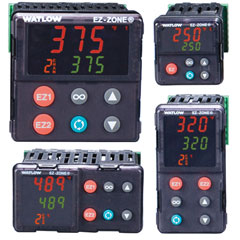
EZ-ZONE® Panel Mount (PM) Controllers
Integrated PID Controller Model Ordering Information
Universal Sensor Input, Standard Bus Communications, TRU-TUNE+ Adaptive Tune, Red and Green Seven-Segment Displays.
The Integrated PID Controller Model comes with all options available.
PID Controller Model Ordering Information
Universal Sensor Input, Standard Bus Communications, TRU-TUNE+ Adaptive Tune, Red and Green Seven-Segment Displays
PID Model does not have all options available; (9) Auxiliary Control Functions & (10)(11) Outputs 3 & 4 are not available.
Enhanced Limit Model Ordering Information
Universal Sensor Input, Configuration Communications, Red and Green Seven-Segment Displays.
Enhanced Limit Model does not have all options available; (9) Auxiliary Control Functions are not available.
Limit Model Ordering Information
Universal Sensor Input, Standard Bus Communications, Red and Green Seven-Segment Displays.
Limit Model does not have all options available; (9) Auxiliary Control Functions and (10)(11) Outputs 3 & 4 are not available.