EZ-ZONE® Expansion Module (RME)
Expansion Module Specifications (RME)
(Select an RME module for additional inputs and outputs and higher amperage outputs.)
Requires 24 to 28VAC/VDC power supply, includes communication port for configuration with EZ-ZONE configurator and PC.
Specifications
Line Voltage/Power
- Power consumption: 7 W, 14VA
- Any external power supply used should comply with a Class 2 or SELV rating
Serial Communications
- All modules ship with standard bus protocol for configuration and communication with all other EZ-ZONE products
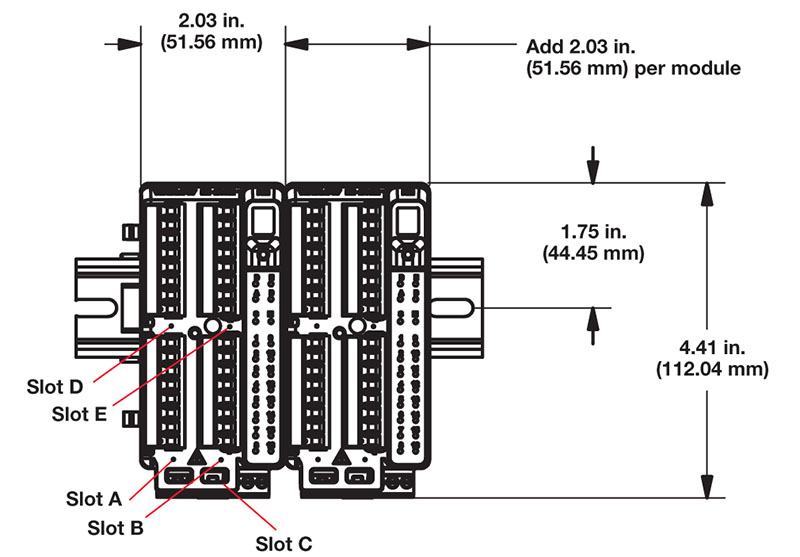
Wiring Termination—Touch Safe Terminals
- Right angle and front-screw type terminal blocks (slots A, B, D, E)
- Input, power and controller output terminals, touch safe, removable, 12 to 30 AWG
- Ring lug terminal blocks (slots A and D only)
- Input, power and controller output terminals are touch safe and removable
Digital Input
- Update rate 10Hz
- Max. input 36VDC at 3mA
- Min. high state 3VDC at 0.25mA
Dry Contact
- Min. open resistance 100kΩ
- Max. closed resistance 50Ω
Output Hardware (6 digital inputs/outputs)
- Update rate 10Hz
- Switched dc
- Output voltage 20VDC max.
- Max. supply current source 40mA at 20VDC and 80mA at 12VDC
- Open collector
- Switched voltage max. 32VDC
- Max. switched current per output 2.5A
- Max. switched current for all six outputs combined 10A
Dual Solid State Relay
- Two SSR board option, Form A, 10A max. each SSRs combined @ 24VAC min., 264VAC max., opto-isolated, without contact suppression, max. resistive load 10A per output at 240VAC, max. 20A per card at 122°F (50°C), max. 12A per card at 149°F (65°C)
Four Mechanical Relay
- Four electro mechanical relays, Form A, 5A, 24 to 240VAC or 30VDC max., resistive load, 100,000 cycles at rated load. Requires a min. load of 20mA at 24V, 125VA pilot duty
Tri-Process (Three universal process/retransmit outputs)
- Output range selections: 0 to 10VDC into a min. 4KΩ load
- 0 to 20mA into max. 400Ω load
Quad SSR
- Four SSRs at 2A each. SSRs are grouped in 2-pairs with each sharing a common.
Programmable Application Blocks
Compare
- Greater than, less than, equal, not equal, greater than or equal, less than or equal
Counters
- Counts up or down, loads predetermined value on the load signal. Output is active when the count value equals or exceeds predetermined target value
Linearization
- Interpolated or stepped relationship
Logic
- And, nand, or, nor, equal, not equal, latch, flip flop
Math
- Average, process scale, deviation scale, differential (subtraction), ratio (divide), add, multiply, absolute difference, min., max., square root, sample and hold, altitude and dew point
Process Value
- Sensor backup, average, crossover, wet/dry bulb, switch over, differential (subtraction), ratio (divide), add, multiply, absolute difference, min., max., square root, altitude, visala and dew point
Special Output Function
- Compressor – turns on-off compressor for one or two loops (cool and dehumidify with single compressor)
- Motorized valve – turns on-off motor open/closed outputs causing valve to represent desired power level
- Sequencer – turns on-off up to four outputs to distribute a single power across all outputs with linear and progressive load wearing
Timers
- On pulse – produces an output of fixed time on the active edge of timer run signal
- Delay – output is a delayed start of timer run and off at same time
- One shot – oven timer
- Retentive – measures timer run signal and output on when accumulated time exceeds target
Variable
- User value for digital or analog variable
| (4) | Connector Style | |
|---|---|---|
| A | = | Right angle screw connector (standard) |
| F | = | Front screw connector (slots A, B, D and E only) |
| R | = | Ring lug connector (if ordered, then slots B and E must be = A) |
| S | = | Custom |
| (5) | Slot A | |
|---|---|---|
| A | = | None |
| C | = | 6 digital I/O |
| F | = | 3 universal process/retransmit outputs |
| J | = | 4 mechanical relay 5A, Form A |
| K | = | 2 SSRs, Form A, 10A max. each (if ordered, then slots B must be = A). |
| L | = | 4 SSR’s at 2A each. SSR’s grouped in 2-pairs with each pair sharing a common. |
| (5) | Slot B | |
|---|---|---|
| A | = | None |
| C | = | 6 digital I/O |
| F | = | 3 universal process/retransmit outputs |
| J | = | 4 mechanical relay 5A, Form A |
| L | = | 4 SSR’s at 2A each. SSR’s grouped in 2-pairs with each pair sharing a common. |
| (5) | Slot D | |
|---|---|---|
| A | = | None |
| C | = | 6 digital I/O |
| F | = | 3 universal process/retransmit outputs |
| J | = | 4 mechanical relay 5A, Form A |
| K | = | 2 SSRs, Form A, 10A max. each (if ordered, then slot E must be = A). |
| L | = | 4 SSR’s at 2A each. SSR’s grouped in 2-pairs with each pair sharing a common. |
| T | = | Quad inputs for external current transformers. Can do either single-phase or three-phase system measurement for all hardware outputs ordered within the expansion module. |
| (5) | Slot E | |
|---|---|---|
| A | = | None |
| C | = | 6 digital I/O |
| F | = | 3 universal process/retransmit outputs |
| L | = | 4 SSR’s at 2A each. SSR’s grouped in 2-pairs with each pair sharing a common. |
| T | = | Quad inputs for external current transformers. Can do either single-phase or three-phase system measurement for all hardware outputs ordered within the expansion module. |
Firmware, Overlays, Parameter Settings
| (11)(12) | Additional Options | |
|---|---|---|
| AA | = | Standard |
| AB | = | Replacement connectors hardware only, for the entered part number. Additional cost for the model can be disregarded as you are only ordering replacement connectors. |
| 12 | = | Class 1, Div. 2 (not available with integrated limit controller or mechanical relay options). |
| XX | = | Custom |